Object-Oriented Model Building
![]() User
Extensible Unit Conversion
User
Extensible Unit Conversion
Reduce redundant data entries with multi-level assemblies.
Simulation users create Project Models and run simulation programs in the SansGUI Run-Time Environment.
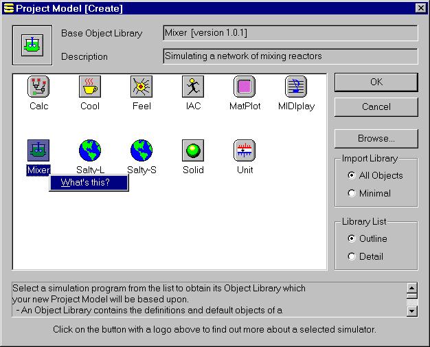
A project model is created based upon one of the installed simulators' Object Library, distributed by the simulation developer. On-line, context-sensitive manuals, if supplied by the developer, can be accessed conveniently.
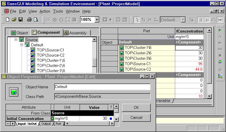
In a Project Model, the model data are organized with objects, and its topographical configuration of parts and links in assemblies. The user creates objects by deriving them from the classes (model building blocks) defined by the simulation developers. The user then places parts and connects them with links on a drawing canvas. These parts and links are derived from common objects analogous to the "Parts List" metaphor in real life products and systems. For example, a user can create a 4"x2"x10' wood stud as a component object and derive many parts (instances) from it. All parts will be initialized with the data from the object. This mechanism greatly reduced the data entry task which no longer requires the user go through each and every part and enter their properties. As shown in the illustration, the class tree (left-right) and the assembly tree (top-down) are "fused" at the leaf nodes (object and parts).
SansGUI has a tri-pane design, which is familiar to users of Windows applications:
The Left Pane contains Tree Views of simulation control and reference objects organized by their classes, components sorted by classes, and components in their assembly structures. The views reflect the hierarchical organization of classes, objects, parts, and assemblies, as shown in the figure above.
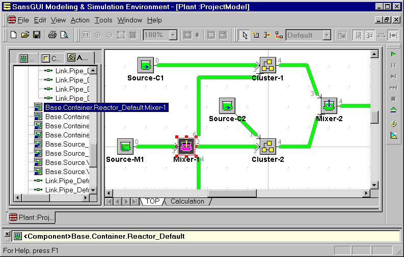
The Right Pane contains Canvas Views of assemblies, where users can create schematic diagrams of the model with parts and links, and Grid Views for lists of objects, parts, and links.
The Bottom Pane contains Operation, Message, and Result Views to allow SansGUI to communicate with the user during simulation runs.
Data in objects are entered via the Object Properties dialog or directly through the Grid View in the Right Pane. The Grid View shows all the objects, parts, or links in the same class so that the user does not have to open their Properties dialogs one by one.
Parts are placed into Canvas Views and links can be drawn to connect parts. SansGUI supports a tree-like assembly structure with multiple levels of parts, links, and assemblies.
Some useful interactive editing features include:
Selecting a group of parts and group move operations
Resizing a part
Cloning a part and its subassemblies
Setting a part's Z-order
Moving components
Multiple levels of undo and redo operations
Zooming in and out
Panning the Canvas View window
Snapping to grid points
Turning labels of parts, links, and ports on and off
Printing and exporting enhanced windows metafile (EMF), bitmap (BMP), and JPEG (JPG) image files
Building completely connected graphs
and many more
The part value overriding mechanism can be used to make small changes at the part level without creating new objects. It reduces redundant data entry and increases data modification efficiency. Together with Symbolic Parametric Values, the user can prepare input data very easily and is encouraged to quickly setup and perform simulation experiments with various input data sets.
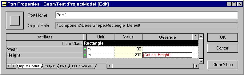
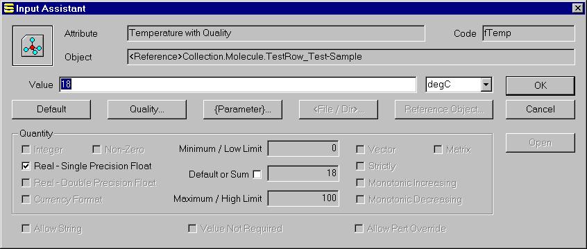
According to the attribute specification given by the simulation developer, the Input Assistant shows the data types and constraints to the user to help data entry. See Qualitative Input Assistant for more helping features.
SansGUI Modeling and Simulation Environment version 1.2
Copyright © 2000-2003 ProtoDesign, Inc. All rights reserved.